Light and Fluorescence microscopy includes a complex series of operational modes that you can select from the panel at the lower left. We suggest that you start with Set-up and Brightfield, but you are able to choose whichever mode you wish to explore. Samples and microscope structure will change to reflect the different applications of the various modes.

MICROSCOPE MODE
SETUP & BRIGHTFIELD
FLUORESCENCE
PHASE CONTRAST
DIC
POLARISED LIGHT
DARKFIELD
CONFOCAL
SUPER-RES – STED
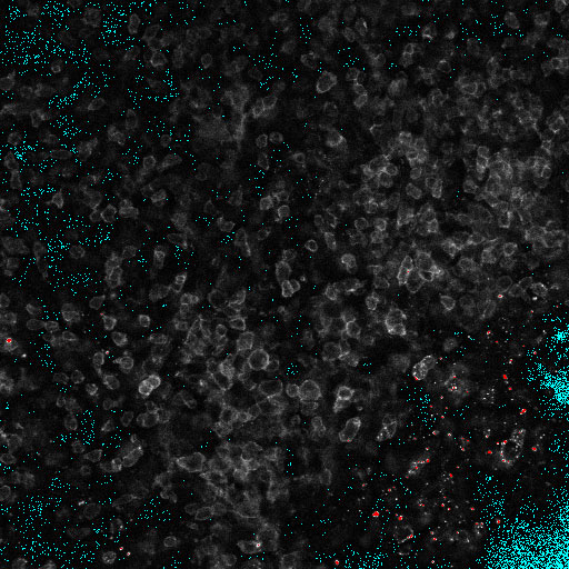
SUPER-RES – SMLM
INSERT
PHASE
DIC FILTER
POLARISER/ANALYSER
DARKFIELD RING
HALOGEN LAMP
MERCURY LAMP
RIGHT EYEPIECE
OBJECTIVES
CONDENSER POSITIONING
Z-STACK & PINHOLE
TOP Z-POS
OPTICAL SECTION THICKNESS
LIVE VIEW
CAPTURE IMAGE
CAPTURE Z-STACK
SCAN RATE (FRAMES/SEC)
0.5
AUTOSCALE
DECONVOLUTION
LIVE VIEW
CAPTURE IMAGE
PIXEL SIZE
120 nm
1x
6x
LIVE VIEW
CAPTURE IMAGE
CAPTURE SMLM IMAGE
DATA PROCESSING
LOW
HIGH
PROCESS SMLM IMAGE
DRIFT CORRECTION
IMAGING SOFTWARE
×HISTOGRAM
×
HISTOGRAM
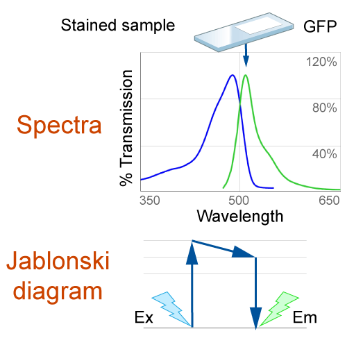
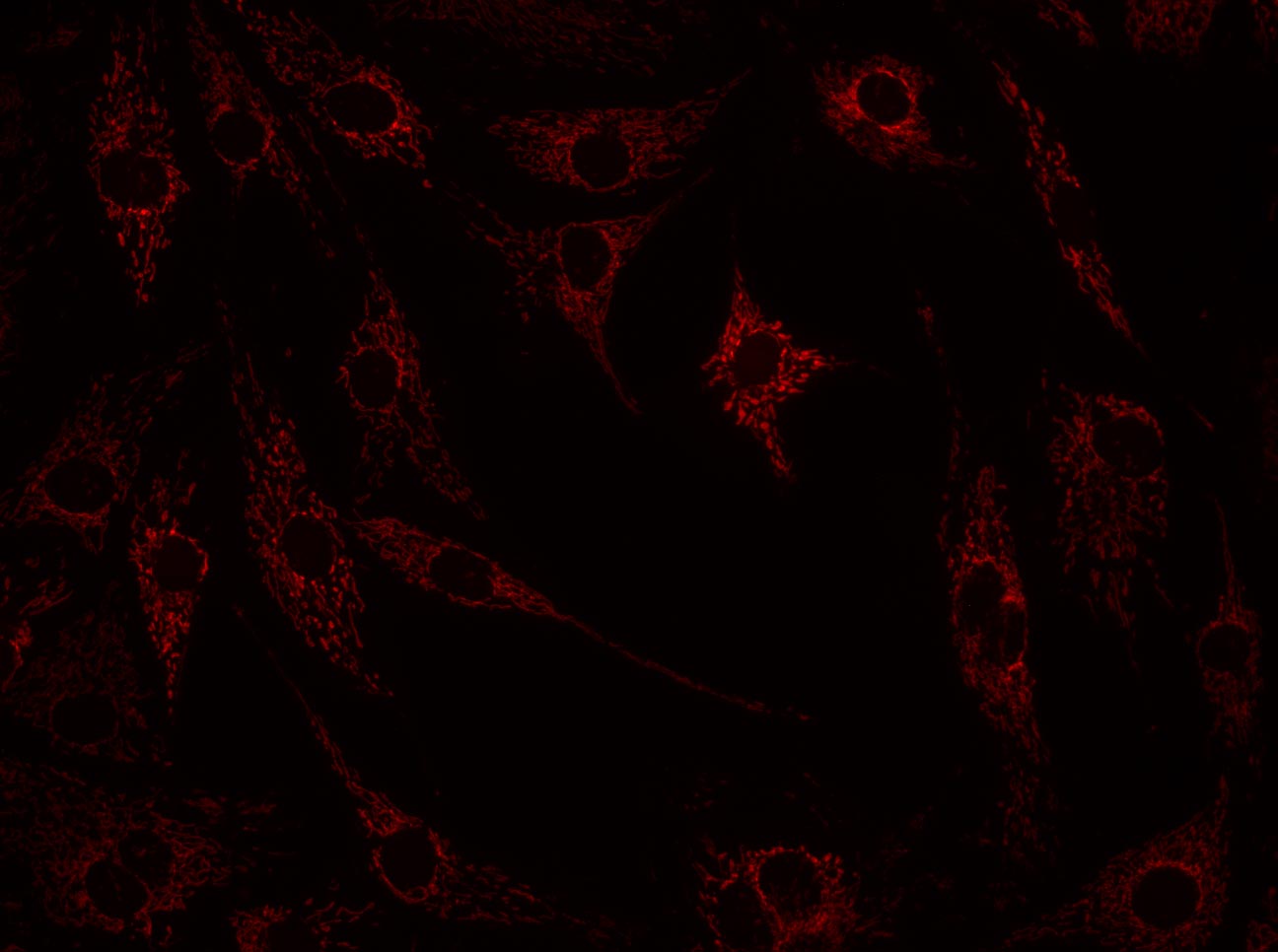
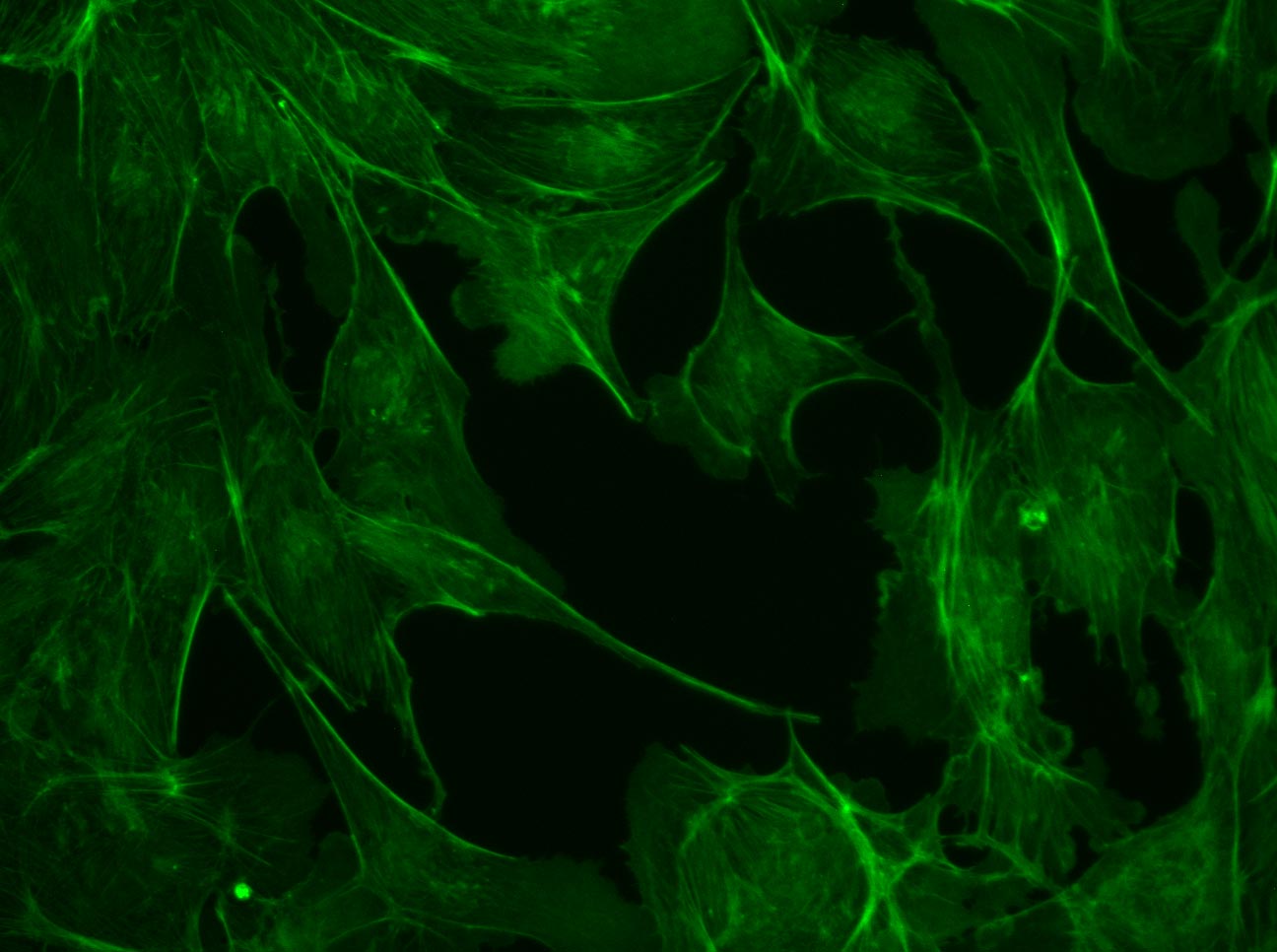
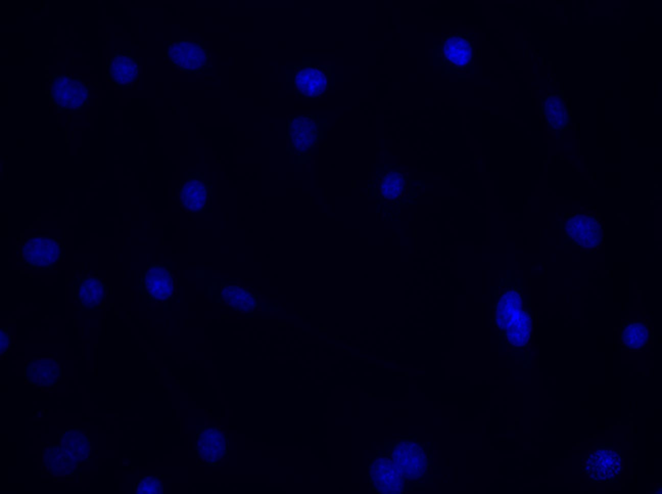
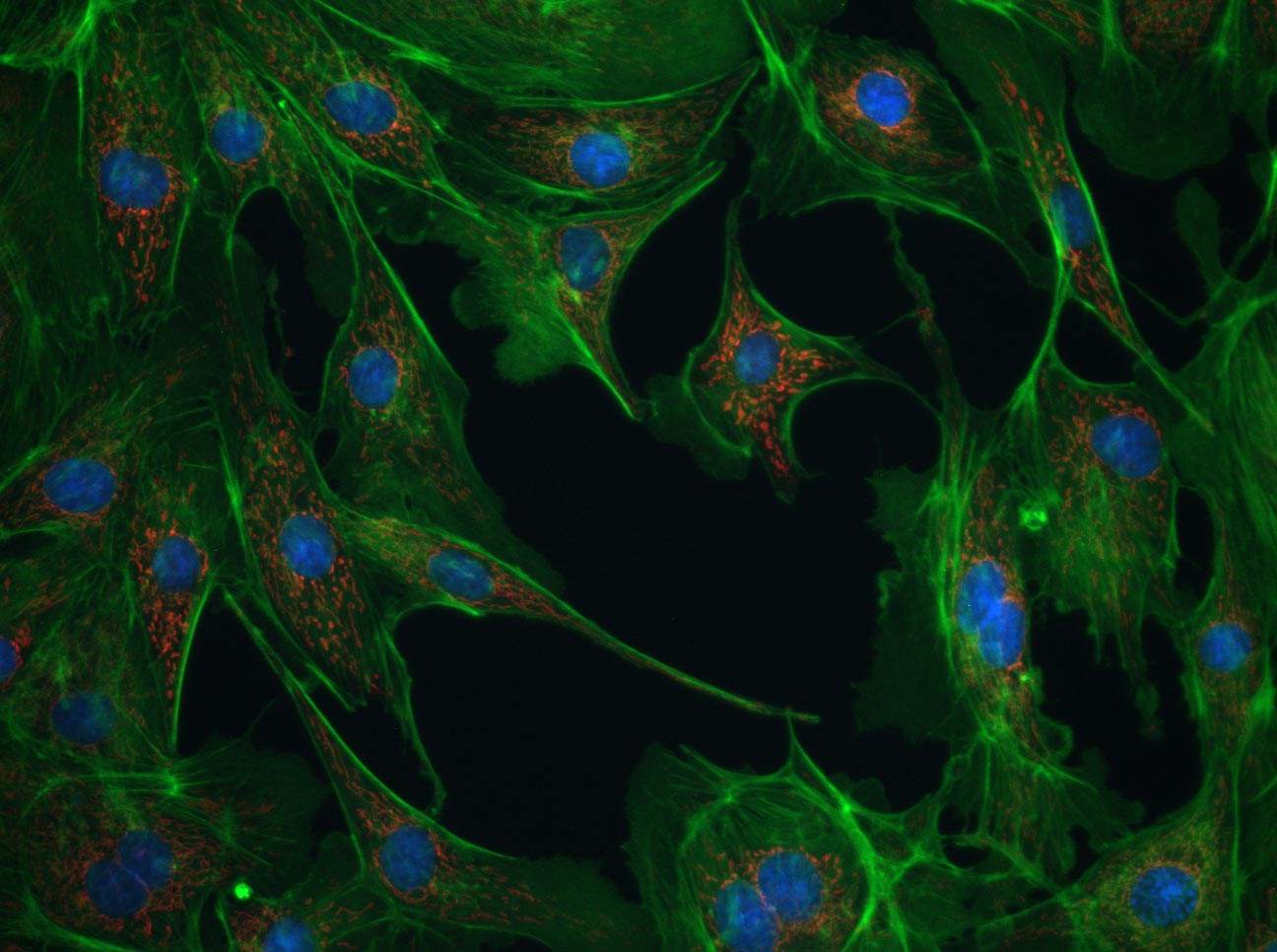
×Excitation–emission: example for viewing GFP
Click to see each channel and then combine the images into the overlay.
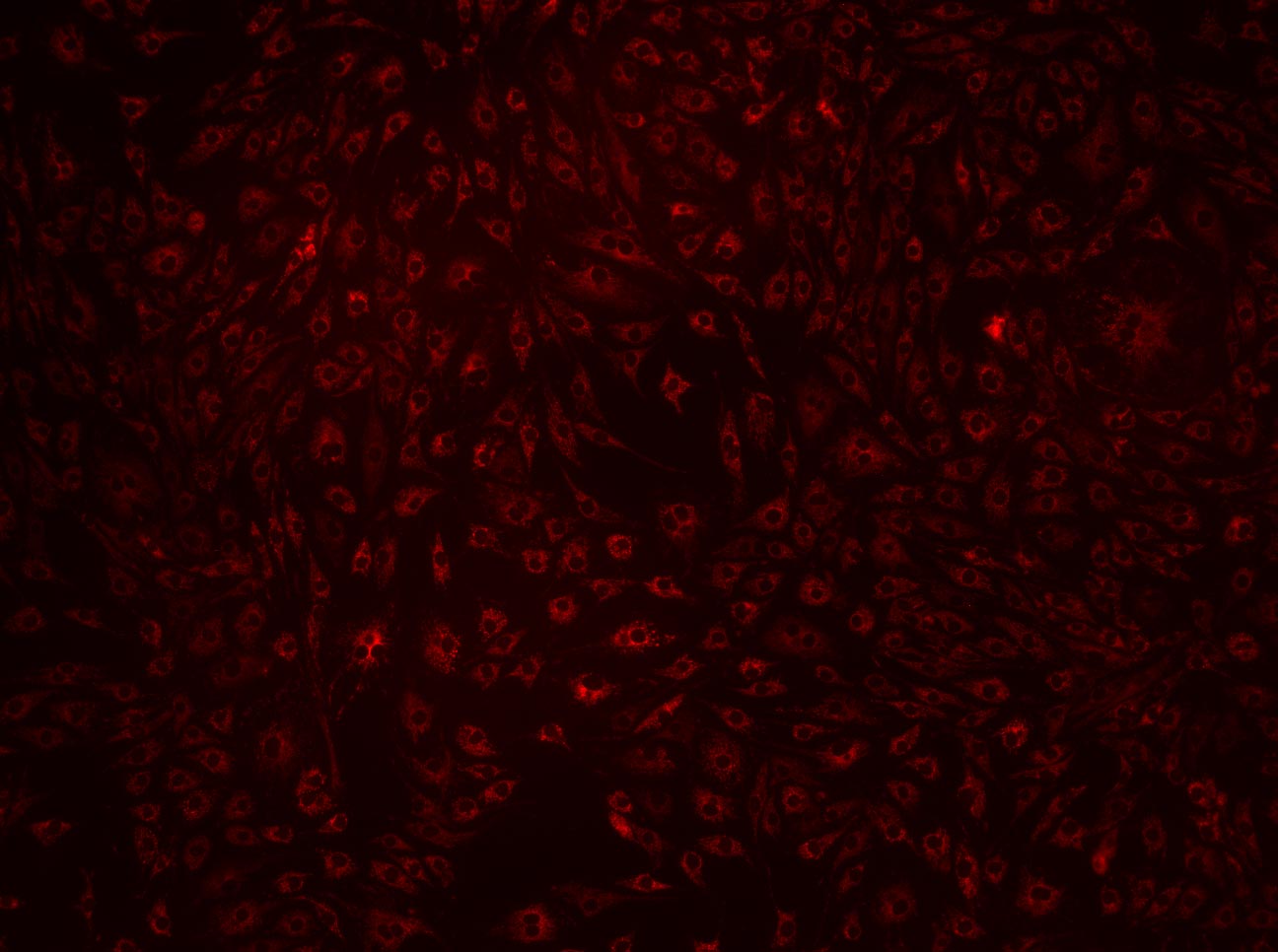
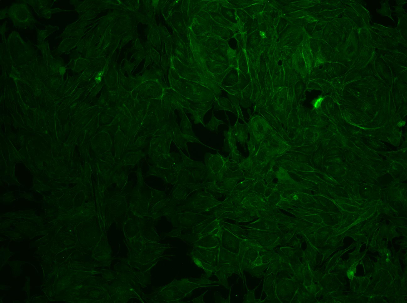

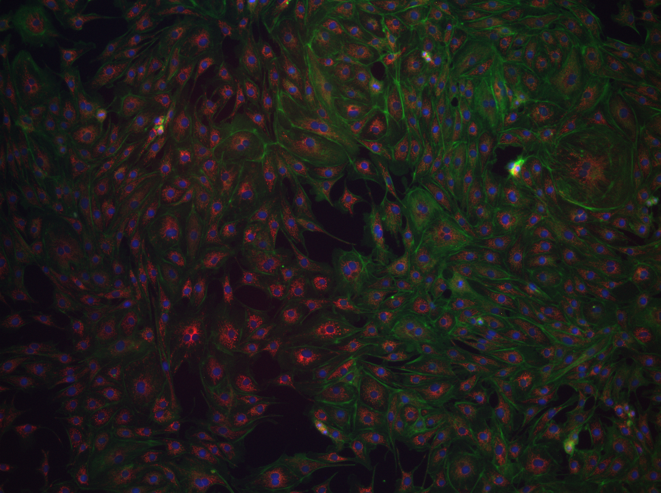
Click to see each channel and then combine the images into the overlay.
Note how much brighter and blurrier the open pinhole image is and how much extra light comes from out of focus planes when the pinhole isn’t blocking it. This is obvious based on number of oversaturated red pixels.
×
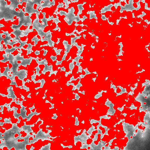
Compare it with the images that you have just collected. If you close the pinhole too much, light can’t reach the detector.
×At a Pixel Dwell Time of 12 µseconds (compared to a dwell time of 2.0 µseconds), the time to collect photons is increased by a factor of 6x. This means the image will be much BRIGHTER and the image scan rate will be much SLOWER. Most common dwell times are around the 2–5 µsecond range.
×The resulting image is a merge of both AlexaFluor568 and AlexaFluor647.
Save this
image to compare it to a sequentially acquired image.
The resulting image is a merge of both AlexaFluor568 and AlexaFluor647 but scanned sequentially.
×Simultaneous
Sequential
×Note that each image is acquired frame by frame to ensure the absence of the spectral bleedthrough of the 568 into Channel 4 that was present in the simultaneous image.
×CONFOCAL
STED
×Use the zoom buttons to have a closer look into a specific region and drag over the image to pan.
When ready close this window to continue.
Lower (6%) STED laser intensity
Higher (35%) STED laser intensity
Higher (35%) STED laser intensity
(with autoscale)
Use the zoom buttons to have a closer look into a specific region and drag over the image to pan.
When ready close this window to continue.
Channel 3 3D image projection and rotation.
×Please wait while the image scans
Diagram
×
Important Points:
×Loading resources
For an optimal experience:
×We recommend you use a larger screen for a good simulation experience.
Geological polarised microscopes have more control features to collect images like these.
In cross-polarised light, the Birefringence colour or shade changes as the mineral is rotated because the proportion of polarised light being conveyed along the mineral optic axes changes with reorientation of the mineral. Plagioclase or pyroxene appear black in cross-polarised light when one of their optic axes is aligned with polarised lighting. The striping in both pyroxene and plagioclase is due to twinning. Lamellar twinning is obvious in plagioclase, with repeated thinly spaced changes in birefringence due to stepped changes in crystallographic orientation. Simple twinning can also be seen in some plagioclase grains, where half of a mineral grain has one crystallographic orientation and the other half has another orientation.